 |
Phone/Text
|
|
| Home News Pictures ThumbDrives Privacy SubscribeStar Facebook | ||
Instructions for the X2 and X2D Mini Mill Tachometer.This is a very easy unit to install.
|
||
Terms used.Control box: The electrical box on the mill head with the E-Stop switch, speed control knob, pilot light and fuse.Controller box: The electrical box on the back of the milling machine.
|
||
Step 1. Unplug your mini mill and all accessories attached to it. |
||
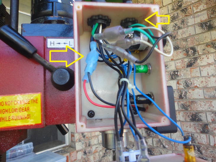
Step 2. Remove the cover of the Control Box and put the screws in a safe location.
|
||
Step 3. Remove the cover of the Controller Box and put the screws in a safe location. |
||
Step 4. Follow the conduit from the motor to the control box, unplug the motor wires inside the control box and remove the ring that secures the conduit to the control box. Slide out the wires (Green, White and Black) and lay that conduit out of the way. |
||
Step 5. Remove the 3 screws that hold the control box to the mill head and set them in the safe location. |
||
Step 6. You will notice that in this kit was a thin copper colored wire with a loop formed at one end. Take that wire and insert it loop first from the controller box end of the conduit until it comes out in the control box. You will need to hold the control box straight out from the controller box so the conduit is straight. This will make it easy for the wire to pass through. |
||
Step 7. strip 1 inch of insulation from the red and black wires that were coiled together. Put one wire in the loop then twist the ends together and fold the end back so it points back to the pair of wires. Carefully pull the red and black wire wires so they are sticking out of both ends of the conduit. You have just completed the hardest step, from here it's all easier. |
||
Step 8. using the 3 screws you removed put the control box back on the mill head. Reconnect the motor conduit and it's 3 wires. (Green to green, white to white and black to black. |
||
Step 9. take the 2 cover screws from the Tachometer head and put them in a safe place. Once opened you will find the other 2 Tach cover screws, 2 button head screws and 2 4-40 screws with washers and nuts, Put them all in a safe location. |
||
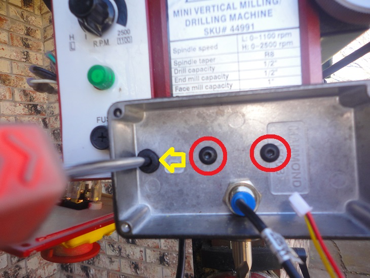
Step 10. Take the back section of the Tach case and mount it with the 2 button head screws as shown. The take a suitable Phillips head screw driver and put it through the grommet as show to mark for drilling a 1/4" hole. Remove this case for drilling so as not to damage the grommet then remount the case. |
||
Step 11. Pass the power wires from the tack through the grommet and in to the control box.
|
||
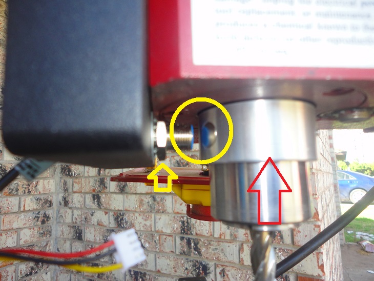
Step 12. Slide the sensor ring up the spindle with the magnet fully over the pickup and tighten the 2 sensor ring setscrews. Now set 1/8" of air-gap. using the 17mm nuts on the sensor, tighten them gently when set. Loctite would be a plus but not required.
|
||
Step 13. There is a chance for error here. Make SURE you hook the red wire to the red wire and have a male connector on one side and a female connector on the other. An easy way to make sure is to leave the connectors paired as shipped when you crimp them. These are fully insulated and may be a pain to get if you make a mistake. The connections are red to red and black to black. Failure to follow this instruction can damage the unit.
|
||
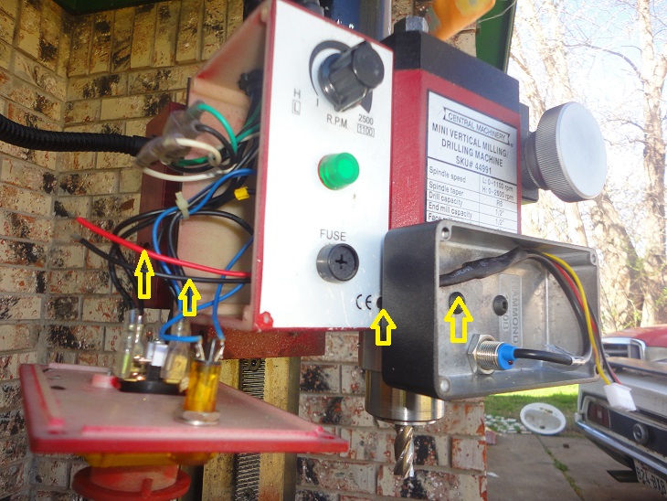
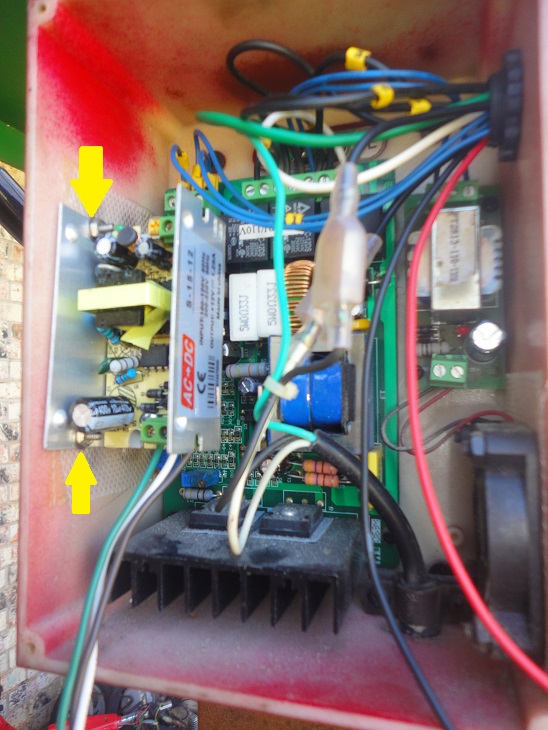
Step 14. Remove the cover from the new power supply. Mount the power supply as shown using the 4-40 screws, nuts and washers. Make sure the power supply does not contact the motor controller board.
|
||
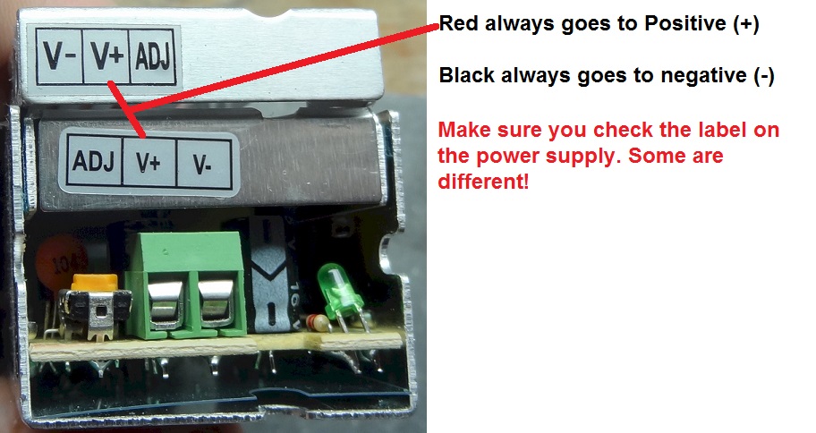
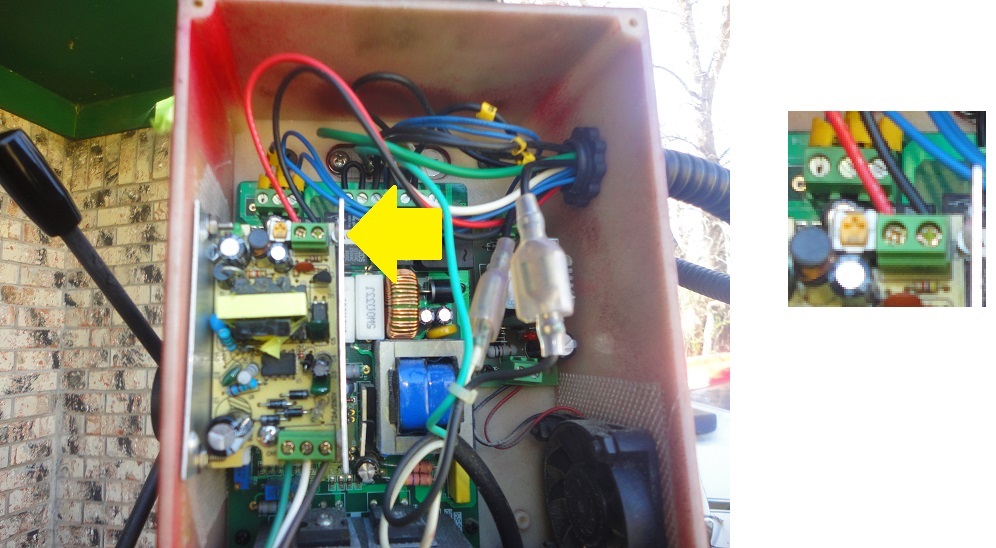
Step 15. Connect the red and black tach wires as shown... Red is Positive, black is negative. Put the metal cover back on the power supply.
|
||
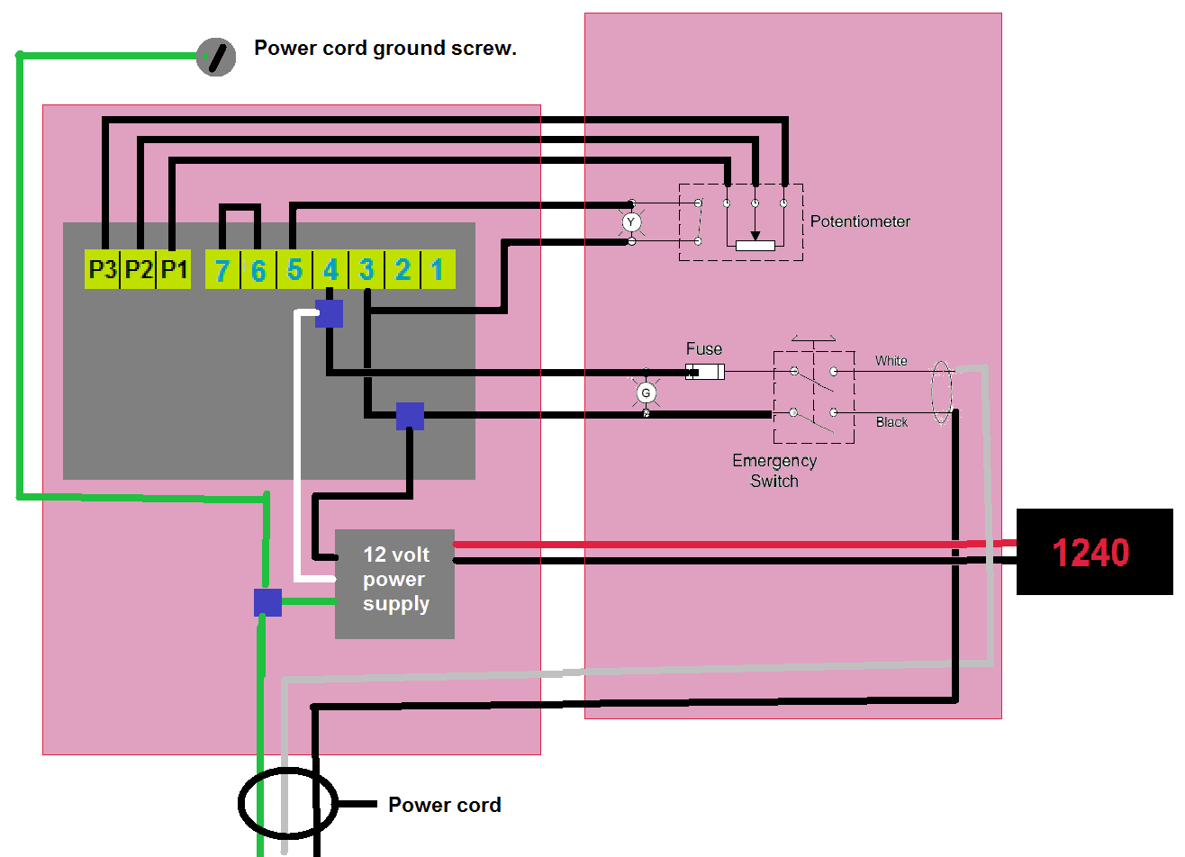
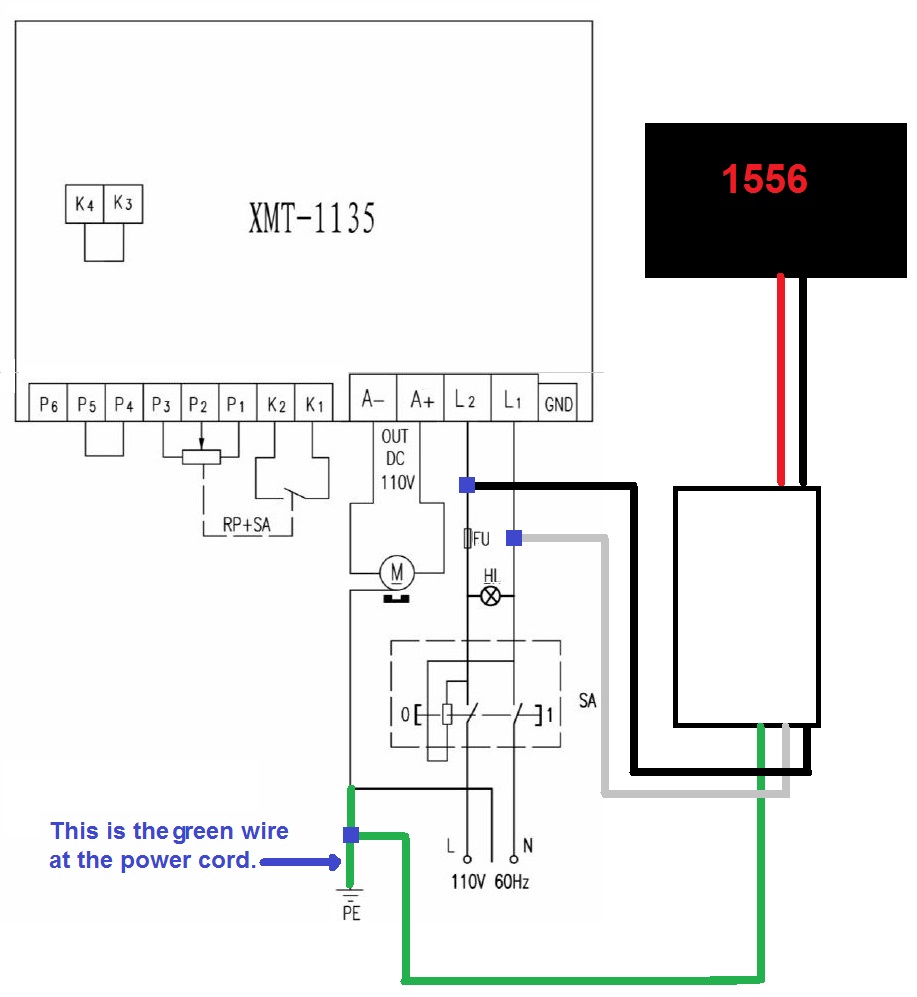
Step 16. Hooking up the power supply to AC voltage... There are 7 terminals on the motor controller board each has wires and the wires have numbered tags. The wires we are concerned with are #3 and #4.The wire tap for the white power supply wire goes on #4 as shown.The wire tap for the black power supply wire goes on #3 as shown.The wire tap for the green power supply wire goes on the wall cord green wire
|
||
|
|
||
|
|
||
|
Home News Pictures ThumbDrives Privacy SubscribeStar Facebook |
||
Copyright 2013-2020 OnCNC.com All rights reserved. |
||